Section 2.3 Circuits
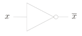
Subsection 2.3.1 NOT gate
This model is inspired by the classical gates with their truth table.

\begin{align}
\begin{array}{c|c}
x & y \\
\hline
0 & 1 \\
1 & 0
\end{array}\tag{2.3.1}
\end{align}
Subsection 2.3.2 AND gate
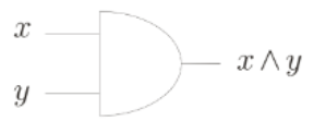
AND logical classical gate and corresponding truth table.

\begin{align}
\begin{array}{cc|c}
x & y & x \wedge y \\
\hline 0 & 0 & 0 \\
0 & 1 & 0 \\
1 & 0 & 0 \\
1 & 1 & 1
\end{array}\tag{2.3.2}
\end{align}
Subsection 2.3.3 Reversible and Nonreversible gate
Since QC is related to a theory of reversible computing, we note that the NOT gate is reversible while the AND gate is not.

With the circuit in the fig. 2.3.3, we can simulate a non-reversible gate, besides, we keep a copy of the inputs and add of the \(x_0∧x_1\) operation, after it adds previous result to \(x_2\text{.}\) We fix \(x_2 = 0\) and obtain a non-reversible AND gate. Where \(\oplus\) represents the logical exclusive-OR operation, which it is the same addition modulo two. Then, we can obtain a reversible version of the circuit if we replace the irreversible parts with their reversible counterparts.


